Tuesday, November 28, 2006

11/28/2006 update:

This past weekend I did indeed get some “me” time to work on my bot. I spent most of Friday making the cables and soldering the interface board. I decided to use ribbon cable (old IDE cables) for the point to point wiring versus wire wrap. I really like the way it worked out and can recommend other give it a try too.

I decided against creating four 8-pin cables from the port headers on the MAVRIC to my interface board. Instead, I designed it so that I used all of PortB for one cable and a combination of PortF, PortE and PortD for the other. In other words, I went the wiring harness route.

From left to right, simple switcher power supply, MAVRIC, interface board, encoder, DC gearmotor

I also decided against reusing my tank base for this bot. The vacuum cleaner belts were starting to dry rot and I really wanted to redo the mechanics of the drive. I spent the rest of my weekend looking for solutions to couple the motors, wheels, and encoders. When I finally settled on gears I then began the search for affordable gears. www.servocity.com have a nice selection, but they are very proud of their gears. $4.95 for 1 gear and it doesn’t even have a set screw not is it bored for the ¼” shaft. Instead they want to sell you a hub for another $4.95. I have a micro lathe and can make my own hubs, but $4 is too much for a single gear IMHO. I found Stock Drive after trying www.servolink.com (great prices but $30 minimum order) and MSC (no details on the gears). They hit me with a $3.95 handling charge for using the online store and then another $6.18 for UPS for 4 freaking gears. The gears were reasonably priced at $2.10 a piece. If they had offered USPS I would have picked that. It’s a major pet peeve of mine getting overcharged for shipping. But I digress.

Oh, and I also ordered some wheels ($10 minimum order) from www.budgetrobotics.com . After deciding on the gears, I was able to knock up a model in CAD. The silver motors will be aligned with the center of the 9" diameter disk platform. The red encoders will be linked via the gears. The wheels will be attached to the gear on the motor shaft via 4 screws. I am planning for the gears to be a press fit, but if not, the hubs on the gears or thick enough to drill and tap for a set screw. Failing that, I'll bore out the hub and make a sleeve hub out of aluminum.

Onward,

Jay


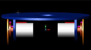
This iso wireframe shows how the gears come into play. The base is made from 6mm pvc.


Wednesday, November 15, 2006

11/15/2006 progress:


What have I been up to? Well mainly I have been thinking about how to physically interface my sensors and peripherals to the MAVRIC. The MAVRIC has 6 8-pin headers (he offers screw terminals too) for each port of the ATMega128 cpu. I am being playing with my pin layout to consolidate as many pins on a port as I can. Some pins are too specialized for this (A2D, UART) and thus I have it down to 4 ports.

Also I have three serial devices but only two serial ports. I need to play with bit-banging to one of them (most likely the voice module).

I have not touched the bot in over a week, but I did place an order to www.sparkfun.com for some odds and ends. This weekend I am testing for level three in Krav and then I’ll work on a interface board. But then I’m still in a circle. Do I need an interface board, or do I create custom wiring harness with 5 8-pin connectors on one end and sensor connectors on the other. Or do I create 4 8-pin bus connectors to a connector board and tie the port pins to their connectors using wire wrapping or point to point soldering and then run another connector from the board to the sensor. I like the second method better but it’s more connectors and thus more to screw up.

Here is what my connector board looked like on a previous robot: http://www.geocities.com/jaydmdigital/ieee/jamaica.html 3rd picture.

After I get the whole connector thing decided, I can work on the PID, line sensors, IR sensor, etc… so you see it really is a key decision.

Hmmmmm…

Jay

Thursday, November 02, 2006

11/2/2006 progress:

I tested my PWM code (and corrected a typo in my blog) tonight. I’m happy to report that locked anti-phase is working. The “sings” at the locked position but I can live with that (I think). Hopefully it won’t be louder than the voice chip speaker. Also, using my RC wattmeter my motor never goes above 1A even with a locked rotor (i.e. my stopping it by hand) with a 12V motor source.

So next on the agenda is PID testing. Then onward to line following.

Onward,

Jay

Wednesday, November 01, 2006

11/1/2006 update:

Things have slowed a bit. I decided that the best way to test the line following was to have a moving platform. Therefore I decided to rebuild my H-Bridge circuit. I decided to compare the circuit I built nearly a decade ago with the reference design. Wow, not sure what I was thinking but my component values for the RC blanking circuit were way not right, and my current sense resistor wasn’t even connected.

Locked anti-phase
Previously I was using PWM of the enable pin for speed control and the phase pin for direction. Recently I read about PWM of the phase call locked anti-phase control. At 50% the motor is locked and thus neither moves forward or backward. If the PWM is less than 50% then it moves backward, greater than 50% forward. How much greater or less than 50% controls the speed. So now you get speed and direction with one control line.

New circuit
I soldered up my new circuit with more correct values except the current sense resistor. RS doesn’t carry a .5ohm resistor and paying $5 for a resistor is nuts. Long story short 10ohms was too big and I ended up removing the current sensing and blanking components from the circuit to make it work. Also I need to get a smaller tip for my iron as I had a short (or two) that I had to trace down too. Once I’m sure on my circuits, drafting a PCB seems like a good idea.

Testing
To test my circuit I first tried it as a servo. I must have been high from solder fumes because I knew that PWM of a servo doesn’t use a duty cycle it uses pulse timing (1.5ms for center, 1ms for 0 degrees, 2ms for 180 degrees roughly). So as a quick and dirty I bit banged a 500ms 50% duty square wave. The motor was locked alright but it was singing too. So I tried smaller periods and settled on 50ms. I’m hoping that using the built in phase correct PWM of Timern that I can get a nice smooth 127 steps in both directions with little wasted power at “stop”. I am thinking that I’ll need to add a brake line for each motor to de-energize the motors at 0 speed (50% duty).

PWM
There are 4 timers on the ATMega128 Timer 0 and 2 are 8-bit and Timer 1 and 3 are 16 bit. All are capable of PWM using output compares. If I only need/want 127 steps then and 8 bit timer is enough, but I can see no penalty in using a 16 bit timer either. So here is the scenario. Using the phase-correct mode of operation the period of the waveform is set by the WGMn3:0 bits. Either 0x00FF, 0X01FF or 0x03FF. For 8-bit 0x00FF is what I’ll use. TCNTn will count up to 0x00FF and then count down to zero. If OCRnx == 0 then the output will be zero. Similarly if it is 0x00FF (or TOP) then output will be 1. So first step is to decide the actual period and set the prescaler to get close. The CPU clock is 16MHz. A prescaler of 64 will give us a 4us timer clock source. This means our period will be roughly 2ms (2 * 255 * 4us) or 500Hz. Now we need to configure the Output Compare bits in TCCRnA. We will configure them to 2 (10b) to clear the output bit on up counting match and set it on down counting match. Finally we need to set the DDRx bits for our output pins.

void timer1PWMInit (void)
{
// Set prescaler
TCCR1B = 0x03; // Timer clocked at F_CPU/64

// Init to 8bit phase correct mode 1
TCCR1A = _BV(WGMA0);

// Configure Output compares for A and B mode 2
// output bit will be cleared on match while up counting and set on match while down counting
TCCR1A = _BV(COMA1) _BV(COMB1); ;

// Set DDRB pins 5 and 6 for output
DDRB = _BV(OC1A) _BV(OC1B);

// set motors to 0 or 50% duty for locked anti-phase controller
OCR1A = 0x7F;
OCR1B = 0x7F;

// Enable timer1 overflows
TIMSK = _BV(TOIE1); // enable TCNT1 overflow

}

Onward,
Jay