10/25/2006 progress:
What a good day it turned out to be yesterday. I went home at lunch to fix the serial cable connector. I booted it up and tried the Soundgin software. YEEHA it works! I spent some time playing with the vocabulary by adding my own words to the listing. So now I move on to the line following sensor.
I have decided that each sensor will be individually mounted and wired. I will use 6’ servo leads. I am leaning towards the QRD 1114 part for ease of mounting. I will try analog first.
Still need to get some proto PCB. I’d rather use the solder mask plated thru hole material vesus the RS stuff, but it’s hard to tell what you get if you order it from a B&W photo. Anyone have any part numbers for me to use. I am thinking 4”x 6” or 2”x 3” .1” PTH with solder mask and mounting holes in each corner.
Onward,
Jay
Tuesday, October 24, 2006
10/24/2006 update:
I decided to take a break form programming and build my audio/voice circuit for the Soundgin. I spent about 2 hours Sunday laying out and soldering the circuit provided by the manufacturer. I didn’t get a chance to test it until that night and it didn’t work … well it did make noise, but not what I was expecting. So I had to wait till lunch Monday to do some debugging. Rather than look at the schematic and trace the line, I draw the schematic based on my soldered circuit. I used that link to creating your own graphing paper to generate PCB graph paper (i.e. dots versus lines) spaced at .2” so I could see what I had. Everything was correct but I had forgotten one connection from the low pass filter to ground. I added it after dinner last night and bingo, I get the demo with plays all the allophones to work.
This morning before leaving for work I added a header to allow me to jumper the demo input to ground, and either use 5V for the LM386 or a 9V lead if I need/want more volume. I also plan to play with adding capacitance to the gain pins.
I had hoped to test the Soundgin software with an RS232 to TTL cable I made ages ago for an HC11 Botboard. Unfortunately, I made a guess as to which pins should RX and TX when I soldered my circuit to the header and I guessed wrong ;) Oh well, with my new crimps I’ll be able to redo the cable in no time. You see, I tried to fix it in the field and ended up pulling one of the wires out ... doh!
Well, back to my list. I think I’ll work on #3 next. That’s the line sensor circuit. That will also require #2. Then I’ll tackle #5. I have 5 of the 3252SB chips in my inventory.
Onward,
Jay
Sunday, October 22, 2006
10/21/2006 update:
Progress has been either stopped or else moving backwards. I’ve been down the very dark street of the TWI on an Atmel device. Long story short, I can’t trust the TWI not to freeze and thus block in my code. So I’m dumping it, the I2C LCD (which I think I may have shorted out too L ), and the last few days of my life. Yeah it’s been bad, but on the the good side, I now have a good handle on how to use the debugger.
So, now I’m dropping back to serial for my LCD (only 16x2 and 9600baud versus the 20x4 and 100KHz). I also grabbed a copy of FreeRTOS which has an AVR port though I’ve had to do some work to port it to mega128 versus the mega232. I need to get my srf04 and encoder code (I intend to pull it out of AVRLib to keep it simple) and get a basic system to have the display updating 5Hz, the sonar measuring (pinging) 10Hz using an external interrupt, and the encoder as an interrupt.
Oh, and all my parts for making wires came in as well as my sound chip and components to get that circuit built … too bad I fried my brain (and nerves) on the $^%^* I2C first.
Onward,
Jay
Monday, October 16, 2006
October 16, 2006 to-do list:
Things are starting to get a bit overwhelming for me. I tend to get ahead of myself and end up second-guessing, blue-skying, and just plain day-dreaming. In other words, I stall out until I can procrastinate no longer and I end up doing marathon sessions. In an effort to prevent that from occurring this time, I have decided to create a to-do list and try to link any dependencies so I can see the forest and the trees.
Note not listed by priority.
1. Build some cables and a break out board.
Status: The parts for the cables has been ordered and should be here by Wednesday. I have a PCB protoboard from Radio Shack but it may be too small.
2. Make a sample of the contest board and line for testing.
Status: Not started. Not a high priority but will need it when I test line sensors.
3. Make a line sensor and test different parts and configurations.
Status: I have QRD1114 and QRB1114 parts and can either feed them into the A2D or to digital I/O via an inverter. I have used both and am leaning towards the A2D.
Dependency: Maybe on wire making parts … but not required for prototypes
4. Make a terminal serial cable for debugging with AvrX
Status: Need to get a surplus serial cable. Then just connect the wires to the MAVRIC. I’ll search for one at lunch.
5. Rebuild/build H-bridge circuit.
Status: I have my original (5 years old now) Allegro Micro A3952SB circuit board and some of the newer A3959SB parts. I need to redo the circuit with cleaner wiring.
Dependency: Wire making parts
6. Design the shape and size of the robot.
Status: I found this link to a website that let’s you print your own graph paper. Will start sketching some designs for the wheel layout and base shapes
7. Design the motor mounts and encoder mounting
Status: Currently I have a tank-based mobile platform with the encoders serving as the other end of the tank tread. I will need to design a way to transfer the shaft motion to the encoders without interfering with the wheels. Also, I’d like the make the motor/encoder mount as a module that can be removed/installed as a component incase I ever want to change the base shape/layout.
8. Prototype a circuit that will decode the 1200Baud I/R signal.
Status: No started but do plan to use one of the UARTs on the MAVRIC. Have not decided on photodiode or phototransistor and will need to do some prototyping.
9. Add sound/speech.
Status: Have ordered components but am backordered on actual voice chip. No ETA. Will call manufacturer to get their opinion and may switch to competing product depending on timeline.
10. Build ball launcher.
Status: I have a pretty good idea for the design using a PVC elbow, a brushless DC motor (because I have one), and BLDC controller using a servo output. At this point I don’t have any real size constraints. The module should be sell contained and thus make it easy for me to change position and angle of it. At this point I am looking for the launcher to sit on one side of the robot.
Onward,
Jay
Sunday, October 15, 2006
October 15, 2006 progress:
One step back, two steps forward. I became obvious to me once I started trying to put a few sensors together and control the rate at which they scanned and displayed their data that I need some sort of task scheduler or RTOS. A quick search on Google and it brought up one I had read about but never used AvrX.
So I have sent the last day reading about AvrX and experimenting with shoehorning my existing sensor drivers into it. After some initial issues with the makefile I was using I have successfully grafted the encoder, i2c, and matrixglcd functions onto some example code Larry provides. I love quick wins it just boosts my morale.
So now that the quick and dirty is out of the way, I am reading everything I can about how and when to use the AvrX api. I have joined the Yahoo Groups support group as well. I hope to have the SRF04 code added by tomorrow. However, it looks like I may want/need to make a serial cable to enable debugging first.
Onward,
Jay
Thursday, October 12, 2006
October 12 progress:
I got the AVRLib i2c library test working and then molded in into what I needed. To do this, I created a i2cLCDsendbyte function to replace the uartsendbyte in rprintf. Now I’ll remount the processor, the new power supply, then new LCD (122x32 or 4x20 with the option of using a 240x64 model I have), the servos and an interface board (when my parts order arrive). If I have time tonight I will modify the SRF04 and encoder programs to use the i2cLCD functions.
Onward,
Jay
Wednesday, October 11, 2006
October 11, 2006 progress:
Microcontroller: The replacement parts have arrived from Brian but looking at how small they still are I’m a bit hesitant to try and solder them in just yet. Besides, it’s working fine without them. In truth I’m going to wait till this weekend when I have some free time at home.
As for programming, I now have quadrature encoding working flawlessly between ARVlib and my 1000PPR encoder. The nice thing about the encoder lib is that it keeps track of the position of the wheel (signed number of ticks) either forward or backward. Next step I2C to graphic LCD. That and I plan to modify my SRF04 code to be standalone from AVRLib for posting on AVRfreaks.net
Voice: I pulled the trigger and ordered a Soundgin (backordered according to the vendor I ordered it from) and the parts to build up a protoboard circuit (amplifier, low pass filter, etc…) most of the parts I found at www.hobbyengineering.com
Odds and ends: Connectors is always something in the back of my mind. Therefore I also made a order from www.action-electronics.com for some Molex KK shrouds, pins, and headers. I won’t have to worry about connectors ever again :)
Onward,
Jay
Monday, October 09, 2006
October 8, 2006 progress
Sunday was 4 hours of yard work and a very unhappy little boy so minimal progress was made. I decided to research speech chips and got off on all kinds of tangents. Makezine.com BLOG is addictive and I was up way too late Saturday night reading it.
So anyway, in a former life I was a midnight engineer for a buddy’s fledgling company. I had designed and programmed a device to translate the clock synchronization signal of one master clock to that of a tower clock controller. This was going to be a big product for his company so he had several PCB’s manufactured along with several sets of parts. Unfortunately the company went bust. I was contacted by the major investor and asked if I wanted the leftover electronics stock before it was “tossed”. Long story short I have a surplus of PCB’s, LCD’s, relays, etc… The reason I explain all this is because I had designed the system to use a switching power supply and had designed the 5V DC supply in one corner of the board. A few minutes with a hack saw and I had a nice PCB for a 5V DC switching PS. I also had all the parts to stuff it and as luck would have it, the diode bridge layout matched the .156” power header part. So, now I have a very stable high current PS (5A IIRC) that I can power from my stock of RC batteries (LiPo and NiMh up to 18VDC IIRC). I will go back any look at my notes to see what the design criteria were, but the system was capable for switching 4 relays at the same time if need be.
Back to the speech chips. Devantech’s is too expensive (at least for now) so it’s down to the SpeakJet or the new (and as far as I can tell not yet released) Savage Innovations Soundgin. Interestingly Magnevation which makes the SpeakJet is a partner in some fashion with Savage and both chips are very similar in that they use phonemes to generate speech. They are the same price but the Soundgin’s manual and software have given it a very strong lead on my score sheet. I’ll have to hack together a demo board with amp, but the schematic is presented. Since both use RS232 communications, I will most likely switch to a I2C LCD (a good excuse to play with I2C again) maybe even a graphic one I have laying around.
So, I think I will spend lunch making a parts order for a speech circuit J
Onward,
Jay
Saturday, October 07, 2006
October 7, 2006 Updates
Wow what progress! Slowly but surely I was able to get the SRF04 sonar module working. Not without a lot of lost time on false starts, dead batteries and general ignorance on my part. I have created some notes for you to consider if you are going down the same path.
* The SRF04 outputs a pulse whose width in us = the distance. To scale it to cm divide by 58 and to get inches divide by 148 per the instructions.
* You can use an external interrupt to measure this pulse by storing the timer count on the rising edge and then subtracting the second time on the falling edge.
* External INT0-3 do not allow “Any Edge” triggers (i.e. both rising and falling edges trigger the interrupt) 4-7 do.
* A 16 bit timer has fewer overflows and helps limit erroneous readings
* The timer counts you use are in CPU ticks not us. Depending on how you configure your prescaler a tick can represent .0625us up to 64us. Since your measurement is in us you will need to convert your ticks to us.
* The SRF04 has a 3cm minimum distance (100us) and measurements start at the element, not the PCB
So using Pascal’s AVRLib I chose to use Counter/Timer1 which he configures with a prescale of 64 (each tick = 4us with a 16MHz clock). I also chose to use INT4 which is on PORTE pin4 configured for both rising and falling edges. IN my ISR I check to see if it is the rising edge (PINE PE4 =1). If so, I capture the current tick count (SonarDistance = TCNT1). Otherwise, I set the SonarDistance = TCNT1 – SonarDistance because the TCNT1 is set to count down.
Now all I need to do is write a function that will ping the sonar X times and return the average.
Depending on how much more time I’ll have today, I’ll start on the encoders.
Onward,
Jay
Friday, October 06, 2006
Update for October 05, 2006
Well on the physical front things aren’t so good. I have had chronic back issues (muscle spasms) ever since 7th grade (maybe even before) where I am somewhat debilitated and unable to stand. Yesterday I woke and was not able to stand up without a lot of pain. It’s hard to concentrate when you have a constant pain in your lower back so I stayed home from work.
On the robotic front I made huge strides. The spasms are weird in that the come and go in spurts (Ibuprofen helps to relax the muscles). When I felt a relaxation I went into my computer room to work on playing with AVRLib. Specifically, I wired up serial communication to a serial LCD and servo control.
Serial LCD:
This was cake to wire as the MAVRIC has screw headers from the Maxim 232 chip. The serial LCD from http://www.crystalfontz.com/ can take level shifted 232 or TTL 232. So I enabled the onboard RS232 pullups (via the dip switches) and gave it a try. It worked, but needed some tweaking to allow the LCD to init before sending any text. It would be nice to have a bigger LCD (4 line, 20 chars but anything is better than nothing).
Servos:
Now this was a PITA. Long story short, I already knew to change timer.h to timer128.h to accommodate the Mega128 device. However, I also had to modify the makefile to do the same thing. I had a 3 hour debug session wherein I dragged out my O-scope to watch the pin transition. After I got one working, adding more was cake. The AVRLib allows you to control up to 8 (any port, any pin) servos simultaneously by using the 16-bit timer/counter. Seemed a bit jerky, but that’s probably due to my adding printf statement to show the position of the servo before updating it to the next value.
I also made a mounting board for the LCD, MAVRIC, and servos. What I’ve learned thus far is I need to add two toggle switches. One for the power to the MAVRIC as there is no reset switch and 1 for the servo power. Come to think of it adding 1 more for the drive motors would be a good idea too.

You can see the MAVRIC, serial LCD, two micro servos,
my wire wrapping connections for the servos, oneofthe RC battery packs, and the Ecro ICE Cube JTAG unit.
Onward,
Jay
Well on the physical front things aren’t so good. I have had chronic back issues (muscle spasms) ever since 7th grade (maybe even before) where I am somewhat debilitated and unable to stand. Yesterday I woke and was not able to stand up without a lot of pain. It’s hard to concentrate when you have a constant pain in your lower back so I stayed home from work.
On the robotic front I made huge strides. The spasms are weird in that the come and go in spurts (Ibuprofen helps to relax the muscles). When I felt a relaxation I went into my computer room to work on playing with AVRLib. Specifically, I wired up serial communication to a serial LCD and servo control.
Serial LCD:
This was cake to wire as the MAVRIC has screw headers from the Maxim 232 chip. The serial LCD from http://www.crystalfontz.com/ can take level shifted 232 or TTL 232. So I enabled the onboard RS232 pullups (via the dip switches) and gave it a try. It worked, but needed some tweaking to allow the LCD to init before sending any text. It would be nice to have a bigger LCD (4 line, 20 chars but anything is better than nothing).
Servos:
Now this was a PITA. Long story short, I already knew to change timer.h to timer128.h to accommodate the Mega128 device. However, I also had to modify the makefile to do the same thing. I had a 3 hour debug session wherein I dragged out my O-scope to watch the pin transition. After I got one working, adding more was cake. The AVRLib allows you to control up to 8 (any port, any pin) servos simultaneously by using the 16-bit timer/counter. Seemed a bit jerky, but that’s probably due to my adding printf statement to show the position of the servo before updating it to the next value.
I also made a mounting board for the LCD, MAVRIC, and servos. What I’ve learned thus far is I need to add two toggle switches. One for the power to the MAVRIC as there is no reset switch and 1 for the servo power. Come to think of it adding 1 more for the drive motors would be a good idea too.
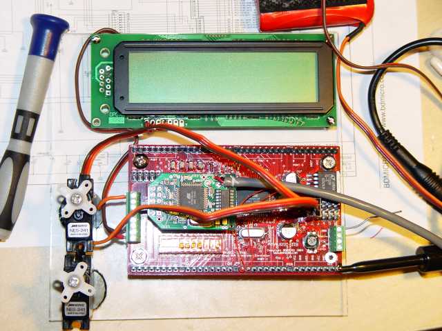
You can see the MAVRIC, serial LCD, two micro servos,
my wire wrapping connections for the servos, oneof
Onward,
Jay
Wednesday, October 04, 2006
Had a chance at lunch to play with the MAVRIC some more. Went through the intro document that comes with WinAVR. Was able to enter a debug session in AVRStudio and step, watch, modify register and program variables. One thing I learned is that everything slows way down from real time.
I then proceeded to debug the hello world program which uses interrupts. Ended up having to modify the program to get any realistic speed, but the program did step as it should. To improve the speed, I will play with breakpoints.
I then modified an AVRLib program using his library to do the same thing as Hello Wolrd. After I figured out the different places I need to check to make sure the right library and target chip is configured it works too. All in all a very productive day.
Next steps. Time to play with some hardware. I will add a serial LCD, a server, and a quadrature encoder. maybe even a push button ... I think I have a "test" board with some LEDs and buttons on it from a Rabbit2000 kit.
Onward,
Jay
Microcontroller board update
Good news, with Brian's (of www.bdmicro.com) patience I have successfully run a test program on the Mavric board. Of course had I done everything right last night I could have reached this step sooner. Here's what all I had to do to get this thing to blink the LED as it should:
1. After soldering the rest of the thru-hole components on the board and getting the go ahead from Brian about the missing (but in the mail) caps I decided on an RC reciever battery (5V DC) to connect the Vcc and GND pins bypassing the LDO regulator.
2. I installed AVRStudio 4 and it's service pack, WinAVR (except PN), and AVRLib
3. Following along with the ICE Cube quick start guide, I atteched it to the JTAG header, connected the battery, and ran AVRStudio.
4. Using the Tools menu I selected AVR Prog to loag the JTAG ICE image to the ICE CUBE. Worked perfectly
5. Using the command line ran make on the Hello World sample from Brian's site. Compiled fine.
6. Using the JTAGICE under Tools programmed the board with the .hex file generated. Programmed fine.
7. Nothing ... no blinking. After an hour or so, I decided to look at it with fresh eyes and went to bed
8. I decided to read the user help in AVRStudio (I know ... wierd isn't it) and read the following under known issues: "ATmega128 in ATmega103 compatibility mode: Not supported, but will be available in a later version of AVR Studio 4." I remembered seeing, reading, something about 103 compatibility mode and found it under the Fuses tab in the JTAG ICE screen. Cleared the fuse and now was seeing a very slow (say 8hz blinking LED). Ok, so it works ... kinda.
9. Read the ATMega datasheet and run ferquency calc in Excel to confirm register settings.
10. Brian's email telling me that the chip has not been programmed for the 16MHz external clock and that the fuse sertting are in the Mavric user manual. DOH! That's where I saw them.
11. Set the fuses per the manual, reset the code fro the Hello World same program ... viola!
Next step, figure out how to use JTAG debugging. Oh, and I've noticed what may be a solder bridge on two of PortB's pins that need to be inspected closer.
Onward,
Jay
Monday, October 02, 2006
Encoders and odometry
Along with knowing how many RPM my wheels will be spinning, I can calculate velocity. With the dimensions of my wheels I can calculate distance. And with the dimensions and layout of the wheels to the center of the bot, I can calculate angle. David Anderson has a great site to dicuss these and showcase his robot SRO4. Be sure to have a look at his writeups towards the end of the page.
Also, I have found a nice lab pdf that uses the AVRlib to do quadrature encoding.
Onward,
Jay
Coding
On the trail of PID motor control I found this interesing library.
This may save me a lot of "reinventing the wheel" and allow me to
concentrate on high level tasks ... just as the author intended ;-)
http://seasight.dforge.cse.ucsc.edu/details/data_acquisition/ATmega128/avrlib/docs/html/index.html
The more examples the better.
Onward,
Jay
Microprocessor Update
Well I learned a few things this past weekend. First and foremost my SMD soldering skills are rusty. We perhaps I’m being too critical of myself. I have never actually tried to solder a discrete component smaller than 0805 and the bypass caps in this kit have to be 0402 or smaller. Smaller than a grain of rice for sure. Anyways, I got through 98% of the SMD components on Friday night but two of the .1uF bypass caps were lost as my tweezers shot them into wherever. I contact Brian to get some replacement parts so maybe those will get here today and I can knock them out later tonight.
As I couldn’t finish the board I decided to wit on the thru-hole parts too. To pass the time I started re-reading my Mobile Robotics book and looking for online content along the lines of PID motor control code using the ATMega128. I found a very promising site (still investigating) at www.drtak.org
I have also been playing with some driving strategies for the course which may end up affecting my base platform’s shape.
Onward,
Jay
Subscribe to:
Comments (Atom)