Sunday, June 13, 2010

I have stuffed the board with 24 super bright LEDs. In fact I have reused the old ones that are still good. They have a warm tone I prefer. You can see the daughter board "on-edge" in this shot. It has two brass lugs that twist and lock into the power buss holders. The holders can be strung with connecting wires so you can have a string of up to 8 (or more with a higher amp transformer) in series.


A side by side comparison. The one on the left is the new design using the warm LEDs. The one in the middle is using the cooler blue LEDs running on AC. And the one on the right is the AC warm LEDs. I can't tell any difference in brightness between the two warm ones like I thought I could. Since I ran out of the cool-colored LEDs, I can't do a full comparison with those yet.


Milled another 2 boards (total of 5) but am only using 4 right now. Measured the current at 285.5mA (~72mA per module). The transformer is rated 9V 1A, but the voltage is 10.71V. That is 3.05 Watts. Compare that to the 18W package marking.

Things are bright and easy to see again. Now I can get back to my projects.


-Jay

Friday, June 11, 2010

Milling a LED light circuit


For the past couple of years I have been reviving some LED tasks lights I bought at Costco by replacing burned out LEDs. Each modules has 24 LEDs and it's tedious to find the 1 in the series that is the bad one. The circuit is a transformer-less capacitive AC circuit and it so poorly designed/built that the LEDs are being overdriven.

My solution was to redesign the modules for 12V DC using 8 parallel strands of 3 super bright LEDs pulling 18mA per strand. This video shows me cutting out the new and improved circuit board.

Enjoy,
Jay

Monday, May 31, 2010

5/31/2010

Been a long time since I've updated this blog. I have been addicted tot he www.cnczone.com and all thing computer controlled for the last 3 years. I have a CNC router and a desire to make things. You've seen my old Illuminames. I was using bamboo boxes from an outlet store. Next I tried making my own boxes with sliding lids, but those were a lot of work. My new version is a CNC cut box big enough to hold a custom circuit board (also CNC milled).

Here is my latest version make from an Australian red cedar that used to be part of a nice patio set from Costco before the weather and bugs destroyed it. Anyway, I plan to custom make these and sell these with all proceeds going to Autism Solution Center.


Other examples are here.

Sunday, August 09, 2009


Hall sensor board take 2. here is how it turned out on the second go around. Tested it with a neodymium magnet and it works perfectly.

Also, I got a lot better result on the soldermask using thinner for the Vitrea 160 paint.
Wart Zapper! Here is a circuit I found on the web. I claimed to zap warts (something I wanted to do. Long story short,

IT WORKS :D

I followed the directions here using SMD parts and adjusting the layout to fit on one side.

Jay

Saturday, August 01, 2009

Hall sensor break out board results:

Well, 1.1mm was just too small :) Never got it to work. Oh well, it was a long shot by hand for sure.

So I redid it for a "bigger " sensor device. Also, I am playing with a soldermask technique I found at www.diyaudio.com. It uses a glass paint called Vitrea 160. The image above I painted it with a narrow drush and avoided the pads. Then let it dry for a day and baked it to fuse the paint.

It's a work in progress as I'm not fomd of the "blobiness" of the paint. Trying to get the glass paint smooth is proving a challenge. I want the paint to flow and level out, but it doesn't. I may have to buy some of the thinner to see how that goes.


This last image shows a test I did using Press-N-Peel blue to mask the pads. I then painted over everything, baked it, and then used acetone to remove the mask (and paint on top. Worked really well, just need to improve my PNP blue techie as the mask smeared (due to too high heat and pressure I'm sure).


Jay

Sunday, July 26, 2009

I new milled circuit. Helping out a guy I met on the web that wanted a circuit milled. This is just a test to see if I can do the SMD pads. With the Widgetmaster and Wolfgang ... yep :) The smallest pads are .254mm wide. This is right off the mill with no "cleaning" of the whiskers of copper. I'm impressed.

Removed by request.

Friday, July 24, 2009

Milled an illuminame for me :D

1/4" Lexan. I bought some ball nose endmills. The rouging pass was with a 1/8" 2-flute end mill. The finish pass was a 1/16" ballnose. The max depth is 1/10". The sign is roughly 8 x 3.5"

I plan to light it from underneath.


Thursday, July 23, 2009

I added a more precise spindle to my CNC router.

I broke down and bought a mount for my Wolfgang spindle to mount it to the Widgetmaster router. Was it worth it? You tell me...


Ran a test circuit to compare...

Tuesday, July 07, 2009

I know, I know ... It's been a long time since my last update. However I wanted to share this one. I was contacted by my alma mater to help them mount a SMD hall effect device. Rather than ask me what would be best, they already ordered the part. It's unbelievably small. How small, 1.1mm square!

Yeah, have a look at what I milled out:


Even closer:


The whole board is about 1.5 inches. There are 2 surface mount capacitors in the bottom right. They are size 805 for those that care :D

I'll update when I actually mount the switch and test it. This is a BGA device (4 balls) ... I've never soldered a BGA but plan to use my hot air station. My other option is to buy a skillet from goodwill and do a reflow.

Jay

Monday, January 12, 2009

As usually happens my attention gets moved from robotics into some subset. IN this case, CNC has my full attention. Most of my adventures are posted at www.cnczone.com versus here. I also have been adding new videos to youtube. I was hoping to get involved with the students at my alma mater to get me back to robotics but it didn't work out.

Jay

Saturday, September 27, 2008

Milling a printed circuit. I have been planning the time when I could mill my own circuits to save the hours of tedious point to point wiring I've done for some of my projects. While it didn't turn out as well as I hoped, I milled my first circuit tonight.


Jay

Thursday, August 14, 2008

Update 8/14/2008

One on my goals is to be able to mill my own circuit boards. I done it using the toner transfer method and etching but I want to use the mill to do it. To do this I know I'll need a faster spindle than the one that is on my mill. So I recently purchased a high speed spindle from Wolfgang Engineering. But, I needed to make a mount for it.

Have a look at the process

Onward,
Jay

Saturday, July 19, 2008

Update 7/19/2008:

Some testing of PCB-gcode on my mill. I added home switches. I mounted the Y axis one but am waiting for my extension kit from CNCFusion before mounting the X.

Anyway here is a short video of a test mill:


Jay

Wednesday, July 16, 2008

Updates July 16, 2008

I have posted some pictures of my mill in it's new home.


In addition, I am getting ready to start milling my own prototype PCBs. For this I have found a free ULP for Eagle CAD that converts the board drawing to Gcodes. It's called PCB-Gcode. In my excitement, I also decided to contribute some time to updating some C++ optimization code for PCB-Gcode output. It works very well as you can see in the sample images I uploaded to my Picasa album.

Now I'm working on a GUI interface using Qt. A small learning curve. More about milling PCBs can be found here.

Jay

Monday, June 30, 2008


A new project.


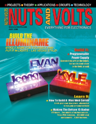
My son took immediate notice of this month's Nuts&Volts cover. Displayed are 3 LED lit name plates ... one being EVAN. "Daddy will you make Evan for me". I jumped at the chance/reason to get my CNC up and running. So I spent Saturday learning/re-learning how to use CAM, Mach3, and my CNC mini-mill.

I used a bamboo organizer box as the base/case and a piece of PVC for the top (that stuff is too useful IMHO). I am using 6 blue LEDS running off a 5 V 270mAh receiver pack (from my RC stash) drawing 20mA.

Of course this is just the beginning, he already want version 2 with blinking/fading lights and knobs and switches.

Edit, not too long after I decided to make some signs for a buddy's little girls. Rather than mill through, I back engraved the acrylic for a nice effect.


Jay

Tuesday, March 18, 2008

Something new:

I leaned something new the other day and decided to give it a go. Charlieplexing is a type of multiplexing for LEDs that allows N pins to control N*(N-1) LEDs. So 5 pins on a Tiny13 can control 20Leds. I used 14 and here is the result:


Update: I tried POV (persistence of vision) but I'm not really clear on what needs to happen for the affect to show up. It was a half-hearted attempt to say the least.

Jay

Thursday, March 13, 2008

Gripper: final version with new video and source code


As promised here is the source code. Also, I hinted at another project I want to tackle .. .that being an electromagnetic levitator. I think the Tiny is up to the task :)

Of course it would behoove me to get my development environment built too. I programmed the Tiny at least 50 times, by removing it from the socket on my circuit. I need to order a ZIF socket, a 6-pin programming cable, and a longer USB cable so I can do ISP and debug wire on future circuits :)

Jay

Wednesday, March 12, 2008

Updates: 3/12/2008:

First let me say that if you are an engineer and a father a great "toy" for both you and your kid(s) is the Snap Circuits kits from www.elenco.com (available at Radio Shack for a premium price). We bought the Jr. kit as my son is only 4 and he and I have already made all 101 circuits in one day. I have since ordered the Extreme kit which should offer all kinds of experiments. it just arrived today :D I recommend you get the Extreme first.

Now back to my gripper controller project. I have decided to continue improving the design some more. Most all my friends that have seen the video have commented that the motion looks too jerky and that it's not obvious that my hand is controlling the position of the servo. To address these I am going to modify the code to only update the servo position at 5Hz even though the A2D is being read at 20Hz. Furthermore, the servo position will only move +- 1 each iteration. I may change this based on the actual movement I see of course. As for the second issue, I'll just shoot a better video and maybe add some explaining :) I also plan to add in another sensor to control the gripper opening and closing the same way.

Forward,
Jay

Monday, March 10, 2008

Update 3/10/2008:

I been MIA working on some paying projects. After I completed that, I got drawn into a new venture with a buddy. I can't say too much about what it'll be, but in order to get ready for it I've been playing with a new chip (to me anyway). The Atmel Tiny13.

Pros:
  • 8-pin dip $1.29
  • No xtal needed has internal clocks up to 9.6MHz
  • Supports in-circuit programming
  • 1K flash, .5k EEPROM
  • 6 I/O all of which can be digital or 10-bit A2D
  • Requires a pull-up on reset
  • Uses the same GCC compiler as I am used to
Cons:
  • Internal clocks while they can be calibrated are somewhat inaccurate (thought they work fine for what I want)
  • 1K of flash goes fast :)
In a nutshell I wanted a servo tester/driver. So I surfed the web, found snippets of code here and there, and came up with a little demo. If I were to use this on my robot, I would change it to trigger a "pickup" sequence of servo moves. However, I've never really played with the A2D on an Atmel and I purchased 4 Sharp gp2d12's so I figured why not. The A2D is read about 40Hz which is also how often the servos get a new value (if required). The timer ISR is set to execute every 13us. At the end of every 20ms frame, the servo signals are turned on. Each run of the 13us timer subtracts 1 from the servo count until it reaches 0. Then the servo pin is turned off. I'm only using the upper 8-bits of the A2D conversion (16-bits adds a lot to the program size and I don't think it's needed). The most current reading is compared to the previous reading + or - 7. This is to prevent the servo from "jerking" all over the place, but it results in visible "stops" in the video.


Here is a video of the results. I may add to it, I may not. The important thing is that on a 1" square PCB I can have a multi servo controller that uses analog feedback to position the servos.

I promise to post the source code once I get it cleaned up (this was just quick and dirty) and commented.

Forward,
Jay